Strengthening the bits

Will the scooter be strong enough to stand on?  Hmm. Perhaps not!

The donor scooter (see second photo) has an existing frame that is perhaps 100mm wide.  The foot board that has been built is about 300mm wide.  The weight of an average human adult would probably fracture the foot board nicely over the frame. Perhaps I should have thought of this sooner?

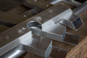
The answer – fabricate a light frame from aluminium to strengthen the foot board.  Ulrich Aluminium supplied some sturdy and inexpensive box section.  I cut two cross members with 45 degree cuts using a regular drop saw with a waxed blade – slowly! – and two longitudinal members to fit over the top of these.  The total aluminium used represents less than $10.

As can be seen in the photo, one of the cross members had to have a section cut away with a hole saw (using CRC as a lubricant on the drill press) to fit around an existing tube on the scooter.  The two longitudinal members had three sides of the box section removed with a hacksaw, file and some elbow grease. Holes were drilled to match existing mounting holes in the scooter frame (for the old plastic foot board).

Fabricated aluminium parts

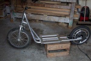
The frame will be mounted in place (in the position shown in the photo) through existing holes in the scooter frame, and the foot board/fairing mounted to this.  I had to cut away a section of sheet steel that was welded to the rear of the foot board area at an upwards angle.  The first time I have used an angle grinder – the sheer amount of sparks gave me a bit of a fright, but no problems there!

Donor kick scooter showing frame in place

You can see the hub motor in the rear wheel. The whole unit is cast as one piece.  It is also on the right way around now 🙂

Boxing the bits

The design of my scooter is fairly minimalist.  It would be great if it didn’t need a battery and controller, but unfortunately it does.  And even more unfortunately they are huge and weigh a tonne.

I decided to house everything in a single box that serves double purpose as the seat.  The battery (about the same size and weight as a car battery) and the battery management system (BMS) live at the bottom, and the controller (with all the cable connections) lives upstairs in a separate compartment.  I’m still waiting on some electrical plugs and bits and pieces to be delivered, but in the meantime have constructed the box.

The box width and depth snugly fit the battery, standing on its end, surrounded by packing foam.  The height is designed for a comfortable seat position, which luckily leaves a nice compartment above the battery for the controller.  The box is constructed of 9mm ply, with 20×20 pine for structural elements, glued together. The front and rear faces of the box are bolted on with M6 bolts that bolt into these whatchamacallits that screw into the timber and have a thread to accept the bolts.  This allows the box to be easily opened for repair if required.  I mean, when required.

Battery box showing charging plug

Battery box open showing controller above battery

Gluing the bits

I’m not one to learn from people’s past mistakes – I like to make them myself.  A lot of them it seems.

The next step, after three hours of mindless drilling, was to cut a zillion spacers out of waste MDF, all exactly the same size.  I cut them around 75mm square (from 18mm MDF).  These were glued edge-wise all around the inner circumference of a former, and another former glued on top.  Lining the formers up accurately was done by gluing the spacer against one of the pencil lines (mentioned in the last post) on one former, and then lining the next former up with the same pencil line.

Once all formers were glued together using the spacers I had my finished form, exactly 300mm wide, ready for lamination to begin.  Mental note: It weighs a ton.

After talking to not enough people, I chose an expensive PVA-style glue called ‘Titebond III’ that is apparently the ducks nuts.  It really is – it can stick anything together, and really fast – unfortunately, when you are laminating you need a lot of working time to get things right, and this glue does not give you that.  Mental note: Next time choose a glue with an open time of 30 minutes at least. Titebond III has an open time of 10 minutes, but I swear that the glue became unworkable after 5.

The first lamination consisted of a 4mm birch 4-ply sheet for the outer layer (also called aircraft ply, or thin birch ply), and a 6mm sheet of bendy ply (also 4-ply).  Glue was spread over the birch ply (Mental note: Use lots more glue next time, and maybe don’t use a roller because it seems to eat the glue) and the birch ply was laid over the bendy ply.  Using Father as a helper, we clamped both sheets in the centre (luckily we had marked the centre of the sheets and the centre of the former) and proceeded to clamp outward one way, and then the other way.  This took close to 30 minutes with 2 people. Mental note: Clamping laminations is not as easy as I thought it would be!

One of the problems encountered early on is that it is very difficult to ensure that the two sheets are tightly mated.  Especially in tight corners, the laminations come apart and a tiny gap forms.  Because part of the work has already been clamped ahead, it is almost impossible to fix this before the glue goes off.  I fixed the worst bits later by unclamping the work and squeezing glue down the gaps (bending the ply against the curve to open up the gap), pushing it down with a scrap of plastic cut off an ice cream container, and clamping it back up.

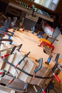
Once all clamps were on, we had the brainwave to strap a strop right around the whole thing and tighten it up.  Genius!  For the following laminations I used strops as the main clamping device, with a few clamps mostly just for positioning.  This is only possible because my form is almost entirely convex.  I would say both methods take about the same amount of time, but using the strops is easier for one person to handle.

Here is a photo showing the first laminations clamped in place and gluing well. Note the strop that we added later to help with the laminations coming apart. Also note the beer crates – great for round the shed.

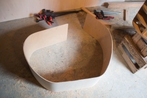
First lamination, all clamped up

Once the work was unclamped, it sprung back about 100mm at each end, but is flexible enough to move back in to place with very little effort.  This was much less spring-back than I was expecting from only the first two laminations.

First lamination, unclamped

Another layer of bendy-ply to go, followed by the final layer of birch ply!

Preparing the bits

The first real challenge (hopefully the only one) to building my electric scooter is fabricating the fairing.  For the uninitiated, the fairing is the part of the scooter that protects you (a little) from wind, rain and crud that flicks up off the wheels.

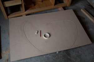
I have decided to form the fairing as a single piece of curved timber by laminating together several sheets of ply, of different types, around a former.  The first part of  this is to decide the fairing shape, and then to cut a pattern from 6mm MDF (Medium Density Fibreboard Custom Wood).  I did this by laying the scooter on top of the MDF and tracing the frame.  The fairing shape was then drawn freehand on the MDF (pencil and a lot of eraser) until the final design was reached.  In the following photo you will see a string laid out along the pencil line.  This is to check that the circumference of the fairing is not longer than the sheet of ply (2400mm).

Checking the circumference with string

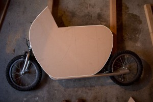
The pattern was then cut out with a jigsaw and the edges cleaned up with sandpaper, taking care to ensure the curves are smooth and flowing.  The following photo shows the finished pattern placed back on the donor scooter for a final size check.  I’ve traced around the image in white to show where the fairing will go.

Checking the pattern for size

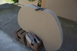
The pattern was then transferred on to a sheet of 18mm MDF by tracing around it with a pencil.  Four of these formers were cut from a single sheet of MDF (1200mm x 2400mm) also with the jigsaw.  Eventually the formers will be evenly spaced (using timber spacers) to provide a total width of around 300mm, which will be the width of the fairing.

The cut formers were stacked on top of each other, lined up as accurately as possible, and clamped together temporarily while they were fastened with 6 long screws.  The screws ensure that the formers are tightly held together while the edges are finished.  Which is of course the next step – using a Palm sander to shape all four formers as one.  Because the fairing will be shaped around all four formers, it is important that they are as identical to each other as possible.

Unfinished formers just before removing clamps

Formers nicely finished with sander

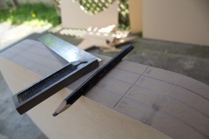
Once the formers are finished with the sander, I marked right across the width of all of them in several places with a set square.  This will help line them up later when assembling the final form with spacers between each sheet.

Markings for alignment

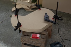
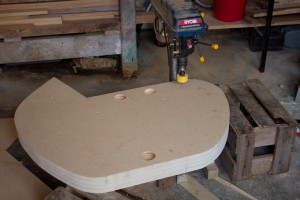
The next part of the process is to drill the holes for clamping.  The flexible plywood will be laminated and bent around the form and will need clamps to hold it in place.  The holes in the the two outer layers of MDF will give the clamps something to purchase.  I am using a holesaw attached to my drill press to drill the clamping holes.  These are around 50mm in diameter.

Drilling the clamp holes

Every journey…

…starts with the first step. Step scooter, that is!

As you are probably well aware if you have spent more than a fleeting second on this site, I have aspirations to one day build my own scratch-built sports car. In recent years these aspirations have been down-graded from a 300km/h hair-raiser, to a single-seater motorcycle-engine driven urban transport, to a chainsaw-driven street legal go-kart, and finally (my current plan) an electric step/kick scooter for the daily commute.

Have to start somewhere, right?

It’s not all bad news though. Building a car is a journey, and because I don’t possess all the fabrication skills I will need yet, starting off small means I can learn the skills and experiment on something less expensive before tackling the next size up.

The donor scooter is a 16″ wheel steel framed scooter more than capable of holding an adults weight. Rather than spend a lot of time on the power-train I have ordered a 16″ wheel e-bike conversion kit direct from China at a ridiculous price. Instead, my fabrication efforts will go into the aesthetics of the scooter, which is much more interesting to me. I’d like to try my hand at wood bending…

Vespa Daniela

Only as good as his tools

I have a project coming up shortly (a gate across the driveway) that has many mortise and tenon joints.  I don’t fancy doing these all with hand tools, so will need to utilise a router.

I have a 2100w Ryobi plunge router (model: ERT2100VK).  It was a ‘must buy’ purchase 3 years ago.  I’ve never used it.

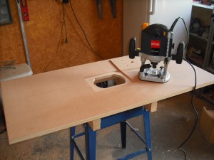
After finding some great videos on trusty YouTube of some DIY router table projects, I decided this was a job I could do myself.  One of the best projects I saw used two sheets of laminated MDF so that the router was attached through a thin plate, but the rest of the table had a good thickness for strength and stability.  That’s the one I based mine on.  The thin plate means that I don’t lose any cutting depth – in fact, the new plate is the same thickness as the old one, so there is no loss in cutting depth at all.

At a local tool shop I found a drop-saw stand that a customer didn’t want when he purchased the saw, so I got it for $40.  It’s nice and solid and makes a great base for the table. Luckily Father owns a portable sawmill, and so the timber for the frame was already supplied

I haven’t quite finished yet – still need father-in-law (electrician) to help me wire in a proper on/off switch (the built-in one will be ok for now), still need a fence (a clamped piece of timber will suffice for now), and still need a router lift (manual adjustment will do for now).

Router table 1
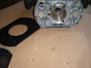
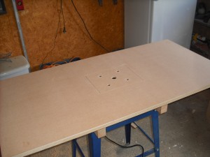
Table with router before installation. Note the laminated surface with a cutout in the top sheet
The existing base plate is removed. This shows the new one with counter-sunk screw holes ready to go on
Base plate attached to the router, with router ready to drop in place
Router in place and ready to roll. Just need a solid piece of timber clamped down for a fence.
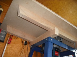
A view from below showing the bracing structure to add strength and support

If anybody knows where to get mitre track or T-track from in New Zealand (especially around Palmerston North) I’d love to know! The closest I have seen is simple aluminium track, but it is not ideal.

Sleep

It has been a long time between updates.  The nursery is complete!

Surprise, surprise – once Wife and I moved Son from our room to his own nursery, we seemed to get a lot more sleep.  I was almost as surprised as Wife when it was done.  It did drag on a bit – Son was already 12 months by the time he got his own room.

Nursery

Time to close the gate

Wife has left me and Son today for a trip to Europe.  For the next 3 weeks I have sole charge of my Son.  I still haven’t finished the TV cabinet.  Or the sports car.  And now with a toddler to occupy my attention I will have even less time for DIY.

So I decided to start another project.

Wife will be thrilled!

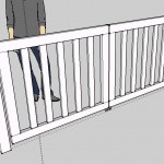
It came to me that I would have more time to finish my projects if Son could roam the backyard with no fear of him toddling out on to the road.  What I need are some gates across the driveway to stop him getting in to trouble.  But of course no ordinary gate will do.  And besides, I have new tools to break in.  So I have decided on double wooden vertical-slat gates on castor wheels with full mortise and tenon joints.

How hard can it be.

Vertical slat gates

But, hang on! Won’t making the gates take time?  And don’t I need more time to finish my current projects?  Sigh.  It’s a bit like buying a wallet with your last cash to keep your cash in…

How to steam punk your baby

I love the steam-punk genre. It’s all dirigibles, flying ships, clunky mechanical robots and Victorian inspired leather clothing.  Of course, I’d look like a plonker dressed up in that stuff, so what better way to live out a childhood dream than to live it out through my (almost) 1 year old son?

I decided to create a replica leather aviator cap (sometimes called a Snoopy hat or flight helmet), complete with flying goggles, for my little boy. I’m sure he’ll love it. CharlesLindbergh would be proud 🙂

1) Search for good images of flight helmets on the internet, and pick one that you like. You’ll need a good front and side view so that you can see how the seams go. I picked the one here because I liked the shape.

2) Paper mâché your baby’s head. Ok, that is not very good advice. Don’t do that. Instead, put a suitable hat on your baby and cover it in strips of masking tape. Enough tape so that when you take the hat off it keeps its shape.

Masking tape to get the head shape

3) Carefully remove the hat from inside the masking tape. It should hold its shape fairly well if you’ve used enough tape. Now add the ear flaps and any other bits and pieces. The inside is still super-sticky, so rip little bits of tissue paper line the inside with the tissue.
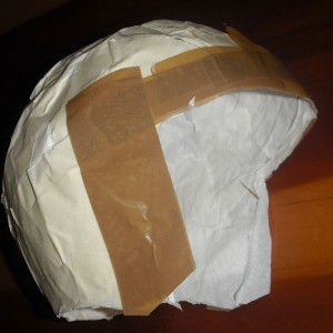
Finished model lined with tissue paper

4) Using your reference photographs, draw seam lines on your finished model, and then *gulp* take a pair of scissors and cut it up along the seam lines.  Flatten the pattern pieces out.  All going well, you should have pairs of almost identical patterns.

5) Because each pair of patterns is not exactly identical, lay them one by one on a piece of paper (in the same spot) and trace around them. Then draw a smooth line (using common sense) to get an average of the two pattern pieces. This is the final pattern. Add a seam allowance (about 1 cm or a half-inch).  Here are my final patterns, including originals. If you look closely you can see the pencil lines of the two original patterns:
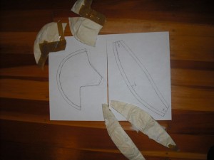
Patterns

Note: photocopy the patterns lightly larger if you are going to use a thick lining material, such as fleece for example.

6) Cut out two of each of your patterns. Use a low tac glue (like a cheap glue-stick) and stick them to the back of your leather, then carefully cut out the leather pieces.

Preparing the leather pieces

7) Now for the time consuming part. Place two of the pattern pieces together (triple check to make sure they are correctly placed before you start). Just a couple of stitches at a time, make the holes with a leather awl and then double-stitch using two needles.  I use a cork place mat behind the work, and instead of double stitch I just go all the way one way and then come back again.
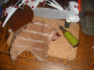
Stitching

8) Unfortunately no photos of much of the rest of the process, sorry!  Continue to stitch the pieces  until the basic cap is ready. It will be inside out with the seams sticking up.

9) Use a good leather cement and glue the seams down flat, splitting them so that each half is glued down on its own side side of the seam. Use a roller (like a wallpaper roller) to flatten the seam nicely if you have one. Trim the ends of the seam if you need to.

10) Replicate steps 6 through 9 with the material you want to use for the lining, but use pins instead of glue when cutting the patterns. I used some relatively thin natural cotton, but you can use a fluffy fleece material if you want to go for that look – just remember to make your pattern a bit bigger so that the lining fits inside with your baby’s head.

11) Turn the lining the right way around and place it over the leather cap (which is still inside out). Using the leather cement, glue the outer edge of the lining to the outer edge of the leather. Now turn it the right side out.

12) Cut a long strip of leather about 35mm wide, and stitch it right the way around the edge of the cap to finish the seam. The leather needs to be folded like the diagram to achieve this. The stitching is difficult because of the multiple layers of leather and fabric, but this trim really helps finish the cap.
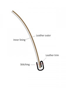
Leather trim

13) If you want a peak, incorporate this in the trim. Instead of a straight strip, cut the trim similar to the diagram below.
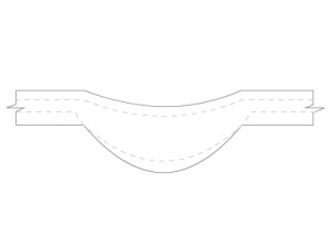
Cap peak

14) Once the cap was ready, I found that the seams around the front of the cap left marks in my son’s forehead because they were not smooth enough. I cut another strip of leather and glued this into the inside of the cap as a hat band, covering all the seams with the soft part of the leather facing the inside.

15) Add accessories! This cap has a couple of straps and a pair of flying goggles made from an inexpensive pair of tanning booth goggles.

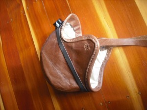
Here is the finished result:

Finished! (1 of 2)

Finished! (2 of 2)

Detail

Bend the brakes!

Before you can bond aluminium into any sort of useful structure, you have to cut and shape the sheets. Now – most of us don’t have access to a fully-furnished metal shop, and a $1000 heavy-duty sheet metal brake is probably not that high up on the shopping list. But don’t worry, there is hope for the DIYer.

I came across these comprehensive plans for a home-made sheet metal brake that look fantastic.  The plans are on biplaneforum.com.  The builder of the brake, Dave Clay from Texas, crafted this tool in an afternoon for around US$75. I see another project on the horizon…

DIY brake by Dave Clay