Category Archives: Urban Personal Transportation

Urban Personal Transportation
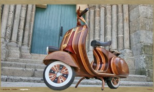
I say: So impractical, I love it!
Wife says: So impractical, I hate it!

Strengthening the bits

Will the scooter be strong enough to stand on?  Hmm. Perhaps not!

The donor scooter (see second photo) has an existing frame that is perhaps 100mm wide.  The foot board that has been built is about 300mm wide.  The weight of an average human adult would probably fracture the foot board nicely over the frame. Perhaps I should have thought of this sooner?

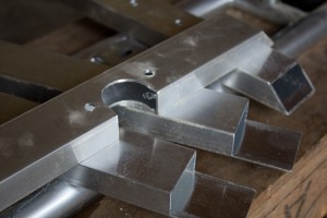
The answer – fabricate a light frame from aluminium to strengthen the foot board.  Ulrich Aluminium supplied some sturdy and inexpensive box section.  I cut two cross members with 45 degree cuts using a regular drop saw with a waxed blade – slowly! – and two longitudinal members to fit over the top of these.  The total aluminium used represents less than $10.

As can be seen in the photo, one of the cross members had to have a section cut away with a hole saw (using CRC as a lubricant on the drill press) to fit around an existing tube on the scooter.  The two longitudinal members had three sides of the box section removed with a hacksaw, file and some elbow grease. Holes were drilled to match existing mounting holes in the scooter frame (for the old plastic foot board).

Fabricated aluminium parts

The frame will be mounted in place (in the position shown in the photo) through existing holes in the scooter frame, and the foot board/fairing mounted to this.  I had to cut away a section of sheet steel that was welded to the rear of the foot board area at an upwards angle.  The first time I have used an angle grinder – the sheer amount of sparks gave me a bit of a fright, but no problems there!

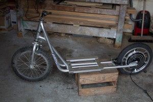
Donor kick scooter showing frame in place

You can see the hub motor in the rear wheel. The whole unit is cast as one piece.  It is also on the right way around now 🙂

Boxing the bits

The design of my scooter is fairly minimalist.  It would be great if it didn’t need a battery and controller, but unfortunately it does.  And even more unfortunately they are huge and weigh a tonne.

I decided to house everything in a single box that serves double purpose as the seat.  The battery (about the same size and weight as a car battery) and the battery management system (BMS) live at the bottom, and the controller (with all the cable connections) lives upstairs in a separate compartment.  I’m still waiting on some electrical plugs and bits and pieces to be delivered, but in the meantime have constructed the box.

The box width and depth snugly fit the battery, standing on its end, surrounded by packing foam.  The height is designed for a comfortable seat position, which luckily leaves a nice compartment above the battery for the controller.  The box is constructed of 9mm ply, with 20×20 pine for structural elements, glued together. The front and rear faces of the box are bolted on with M6 bolts that bolt into these whatchamacallits that screw into the timber and have a thread to accept the bolts.  This allows the box to be easily opened for repair if required.  I mean, when required.

Battery box showing charging plug

Battery box open showing controller above battery

Gluing the bits

I’m not one to learn from people’s past mistakes – I like to make them myself.  A lot of them it seems.

The next step, after three hours of mindless drilling, was to cut a zillion spacers out of waste MDF, all exactly the same size.  I cut them around 75mm square (from 18mm MDF).  These were glued edge-wise all around the inner circumference of a former, and another former glued on top.  Lining the formers up accurately was done by gluing the spacer against one of the pencil lines (mentioned in the last post) on one former, and then lining the next former up with the same pencil line.

Once all formers were glued together using the spacers I had my finished form, exactly 300mm wide, ready for lamination to begin.  Mental note: It weighs a ton.

After talking to not enough people, I chose an expensive PVA-style glue called ‘Titebond III’ that is apparently the ducks nuts.  It really is – it can stick anything together, and really fast – unfortunately, when you are laminating you need a lot of working time to get things right, and this glue does not give you that.  Mental note: Next time choose a glue with an open time of 30 minutes at least. Titebond III has an open time of 10 minutes, but I swear that the glue became unworkable after 5.

The first lamination consisted of a 4mm birch 4-ply sheet for the outer layer (also called aircraft ply, or thin birch ply), and a 6mm sheet of bendy ply (also 4-ply).  Glue was spread over the birch ply (Mental note: Use lots more glue next time, and maybe don’t use a roller because it seems to eat the glue) and the birch ply was laid over the bendy ply.  Using Father as a helper, we clamped both sheets in the centre (luckily we had marked the centre of the sheets and the centre of the former) and proceeded to clamp outward one way, and then the other way.  This took close to 30 minutes with 2 people. Mental note: Clamping laminations is not as easy as I thought it would be!

One of the problems encountered early on is that it is very difficult to ensure that the two sheets are tightly mated.  Especially in tight corners, the laminations come apart and a tiny gap forms.  Because part of the work has already been clamped ahead, it is almost impossible to fix this before the glue goes off.  I fixed the worst bits later by unclamping the work and squeezing glue down the gaps (bending the ply against the curve to open up the gap), pushing it down with a scrap of plastic cut off an ice cream container, and clamping it back up.

Once all clamps were on, we had the brainwave to strap a strop right around the whole thing and tighten it up.  Genius!  For the following laminations I used strops as the main clamping device, with a few clamps mostly just for positioning.  This is only possible because my form is almost entirely convex.  I would say both methods take about the same amount of time, but using the strops is easier for one person to handle.

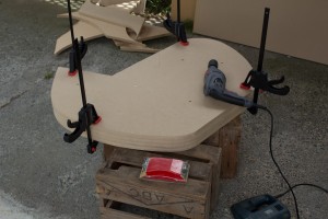
Here is a photo showing the first laminations clamped in place and gluing well. Note the strop that we added later to help with the laminations coming apart. Also note the beer crates – great for round the shed.
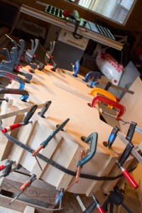
First lamination, all clamped up

Once the work was unclamped, it sprung back about 100mm at each end, but is flexible enough to move back in to place with very little effort.  This was much less spring-back than I was expecting from only the first two laminations.
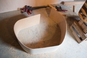
First lamination, unclamped

Another layer of bendy-ply to go, followed by the final layer of birch ply!
Preparing the bits

The first real challenge (hopefully the only one) to building my electric scooter is fabricating the fairing.  For the uninitiated, the fairing is the part of the scooter that protects you (a little) from wind, rain and crud that flicks up off the wheels.

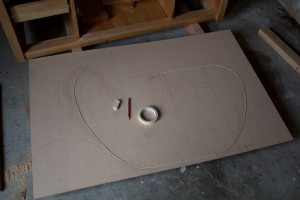
I have decided to form the fairing as a single piece of curved timber by laminating together several sheets of ply, of different types, around a former.  The first part of  this is to decide the fairing shape, and then to cut a pattern from 6mm MDF (Medium Density Fibreboard Custom Wood).  I did this by laying the scooter on top of the MDF and tracing the frame.  The fairing shape was then drawn freehand on the MDF (pencil and a lot of eraser) until the final design was reached.  In the following photo you will see a string laid out along the pencil line.  This is to check that the circumference of the fairing is not longer than the sheet of ply (2400mm).

Checking the circumference with string

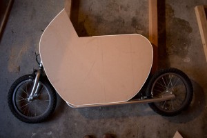
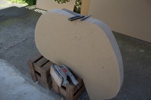
The pattern was then cut out with a jigsaw and the edges cleaned up with sandpaper, taking care to ensure the curves are smooth and flowing.  The following photo shows the finished pattern placed back on the donor scooter for a final size check.  I’ve traced around the image in white to show where the fairing will go.

Checking the pattern for size

The pattern was then transferred on to a sheet of 18mm MDF by tracing around it with a pencil.  Four of these formers were cut from a single sheet of MDF (1200mm x 2400mm) also with the jigsaw.  Eventually the formers will be evenly spaced (using timber spacers) to provide a total width of around 300mm, which will be the width of the fairing.

The cut formers were stacked on top of each other, lined up as accurately as possible, and clamped together temporarily while they were fastened with 6 long screws.  The screws ensure that the formers are tightly held together while the edges are finished.  Which is of course the next step – using a Palm sander to shape all four formers as one.  Because the fairing will be shaped around all four formers, it is important that they are as identical to each other as possible.

Unfinished formers just before removing clamps

Formers nicely finished with sander

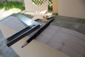
Once the formers are finished with the sander, I marked right across the width of all of them in several places with a set square.  This will help line them up later when assembling the final form with spacers between each sheet.

Markings for alignment

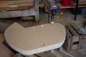
The next part of the process is to drill the holes for clamping.  The flexible plywood will be laminated and bent around the form and will need clamps to hold it in place.  The holes in the the two outer layers of MDF will give the clamps something to purchase.  I am using a holesaw attached to my drill press to drill the clamping holes.  These are around 50mm in diameter.

Drilling the clamp holes

Every journey…

…starts with the first step. Step scooter, that is!

As you are probably well aware if you have spent more than a fleeting second on this site, I have aspirations to one day build my own scratch-built sports car. In recent years these aspirations have been down-graded from a 300km/h hair-raiser, to a single-seater motorcycle-engine driven urban transport, to a chainsaw-driven street legal go-kart, and finally (my current plan) an electric step/kick scooter for the daily commute.

Have to start somewhere, right?

It’s not all bad news though. Building a car is a journey, and because I don’t possess all the fabrication skills I will need yet, starting off small means I can learn the skills and experiment on something less expensive before tackling the next size up.

The donor scooter is a 16″ wheel steel framed scooter more than capable of holding an adults weight. Rather than spend a lot of time on the power-train I have ordered a 16″ wheel e-bike conversion kit direct from China at a ridiculous price. Instead, my fabrication efforts will go into the aesthetics of the scooter, which is much more interesting to me. I’d like to try my hand at wood bending…

Vespa Daniela

Bend the brakes!

Before you can bond aluminium into any sort of useful structure, you have to cut and shape the sheets. Now – most of us don’t have access to a fully-furnished metal shop, and a $1000 heavy-duty sheet metal brake is probably not that high up on the shopping list. But don’t worry, there is hope for the DIYer.

I came across these comprehensive plans for a home-made sheet metal brake that look fantastic.  The plans are on biplaneforum.com.  The builder of the brake, Dave Clay from Texas, crafted this tool in an afternoon for around US$75. I see another project on the horizon…

DIY brake by Dave Clay

Hold it together, man

One thing that has always intrigued me (ok, perhaps not always, as puddles and sand castles intrigued me more as a kid – but at least since I started thinking about vehicle construction) is how metal can be bonded together and still maintain enough strength for the riguors of driving?

Aluminium in particular: Is aluminum bonding something I can do in my own garage, using basic tools, at low cost? Knowing basically nothing about bonding anything heavier than paper, where do I even start looking for the right adhesives and the correct technique?

It all got just a little easier today when I came across the adhesives toolkit – not only does it contain details of how different adhesives perform under different loads and stresses, but has nifty tools (as questionnaires) to help you find the perfect adhesive for your particular situation.

So what to use for a bonded aluminum chassis? Apparently something called Anaerobic Acrylic. What that is? I have no idea…

Lotus Elise aluminium chassis

The bonded aluminium chassis of the 1995 lotus Elise

Footnote: After some additional googling, TA4300 looks ideal.

Star Trekking

Star trekking across the universe
Only going forward ’cause we can’t find reverse

Scratch-built and kit cars based on motorcycle power-plants have long suffered from this Star Trekking ailment. No reverse gear to be found.

Some vehicles utilise a separate gearbox for reverse, or sometimes an electric motor for that purpose.  Others, such as the Peel 50 and the Isetta, had no reverse gear at all, so you had to have a mate handy to push you out of the garage or parking space.

I recently came across a small motorcycle engine (250cc) that has a reverse gear built directly in to the transmission.  This may seem slightly illogical – you’d have to be some sort of stunt devil to ride a motorcycle backwards – until you discover that the engine is meant for an ATV.  Doing some further research proved that this same manufacturer (Lifan, a large and very well known brand in China) has a score of engines with reverse gears.

In the interest of maintaining a list of motorcycle engines with reverse gears, here is the start of my list:

Suggestions to add to the list welcome!

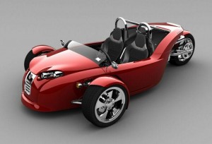
Cirbin V13R reverse trike

Campagna V13R reverse trike
Harley Davidson powered 1250cc V-twin. With mechanical reverse gearbox 🙂

Pasquali Riscio electric

Electricity has it’s attractions.  Electric motors output maximum torque from 1 RPM, so you get maximum power from the get go.  This means acceleration off the mark, even if the vehicle doesn’t have a super top speed (well, not all are slow).  Electricity can be produced cleanly, especially in New Zealand, where hydro power is our major electricity source, and wind turbines surround the city in which I live.  Electric motors are also extremely quiet, and produce no pollutants.

Unfortunately, electricity also has it’s drawbacks.  Range is a big one, especially in New Zealand where population density and terrain mean things tend to be far apart.  Charging a battery also takes slightly longer than filling your average fuel tank.

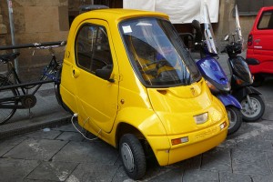
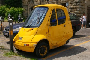
However, sometime it just makes sense.  Take the Italian Pasquali Risció as an example.  A shade over 1m x 2m and only 1.5m tall, one- or two-seater options, 40km/h top speed and a 50km range. Considering it’s meant for urban commuting, this is quite ideal.  Even the 8hr (ouch!) recharge time isn’t too bad if you can just plug it in over night.

My own project won’t be designed to run on electricity per se, but since it will be designed in such a way as to allow a wide range of power options I can’t rule out someone else being crazy enough to try it in the future.

Pasquali Riscio

Pasquali Riscio

Images sources: Lucarelli and Mallady.

Classic inspiration

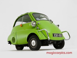
In the early 50’s, when people were nuts, there was an Italian refrigerator-and-scooter manufacturer who decided they wanted to mass-produce a micro car.  The Isetta was born.  Designed and first produced by Iso SpA, variations of it were produced by many manufacturers in many countries.

This tiny egg shaped car was only 2.3m by 1.4m, and powered by a 236cc two-stroke.  To get in, the whole front of the car swung outward as the door, with the steering wheel and instrument panel attached.  It had a top speed of around 74km/h, but apparently took 30 seconds to reach 50km/h!

I love the this quote from Isetta Broker:

It is said that the stylists had arrived at the design of the Isetta by taking two scooters, placing them close together, adding a refrigerator and shaping the result like a teardrop in the wind.

At first I dismissed it as an ugly (but weirdly cute) throw-back, but the more I researched it, the more I have come to like it’s cute 50’s retro style.  Perhaps not a model on which to base my project, but a great early example of the species.

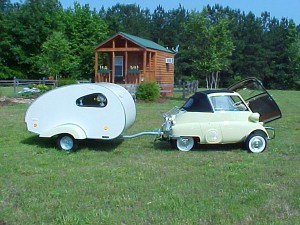
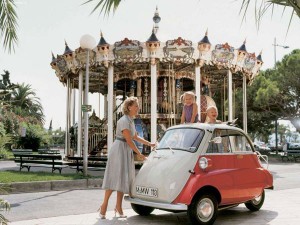
My favorite image has to be the Isetta pulling that tiny teardrop caravan. To really get a feel for how small that caravan must be you only need to take a look at the last image (with the family) to put the scale of the Isetta in perspective!

Isetta with door open

isetta_02

isetta_03

isetta_04

Image sources: Al & Ed’s Autosound, magiccarpics.com, emmiebean, netcarshow.com

More information about the Isetta, visit: Isetta Broker