The important bits

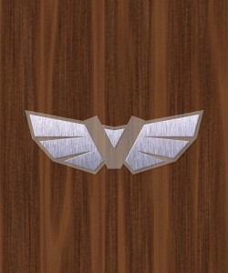
One thing on the electric scooter is vitally more important than all others. What could that be?  The badge, of course!

V badge in black and white

Those that know me will see why I chose a ‘V’.  Everyone else, lets just say its along the lines of ‘Volt’ 🙂

V badge

The badge will be constructed of perspex with aluminium bonded to the surface.  LEDs embedded in the perspex under the alu will give a nice, subtle glow. White at the front, red at teh rear.  Not sure on the size yet, but probably around 150mm across.

The boring bits

Not every minute of a project can be packed with excitement. Sometimes, you just have to get on with it.

The biggest excitement on the project by far last week was ‘test driving’ the scooter to work. As I am still a little dubious about the legal requirements, I took a circuitous route down a path along the local river.  Unfortunately, the section I chose to take was not sealed, and I ended up losing my nuts.  Erm.  I mean, some of the nuts came off the bolts holding the fairing to the frame.  This wasn’t a biggie – there are quite a lot of bolts holding the scooter together.  The final construction will use nyloc nuts.  Some observations:

  • The ride quality is great (except on gravel).
  • Torque was fantastic, even hitting maximum speed uphill.
  • Maximum speed was around 32 km/h. Not complaining, really.
  • The brakes are not that good. Yes, this one is a complaint.
  • The handlebars, already at maximum extension, are a little low.
  • There is not quite enough area for feet. It needs pegs.
  • There is no stand. A problem once I got to work! (No beer crates to lean on – will work on that).

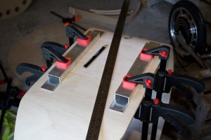
After the fun day test-driving, I took the scooter completely apart again.  The plan is that next time it goes back together will be the final time (with nyloc nuts).  Once again I spent some time repairing peeling laminations that the rigours of the drive bought to light.
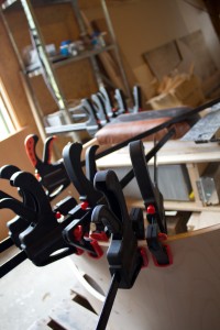
Localised clamping to fix peeling laminations

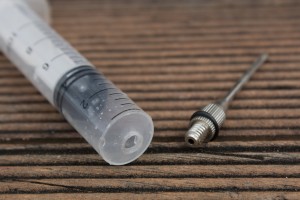
I managed to construct a fairly good glue applicator needle from a 10ml plastic syringe with the nozzle cut off and a ball-pump needle screwed in to the hole!  This fits easily into small gaps and allows me to spread the glue well before clamping.  I use a plastic off-cut from a takeaway container as a spatula to spread the glue in the crack.

Home-made glue applicator needle

Detail of the glue applicator needle

K-Mart supplied a cheap, generic, extendible kick stand.  On testing it, it was miles too long, so I threw away the extension and put the hacksaw to use making it shorter.  My plan is now to buy another one, cut it the same and put it on the other side.  They are the right length to stand the bike vertically (rather than leaning).  I may also look at some sort of steering lock so that the front wheel doesn’t move while parked.
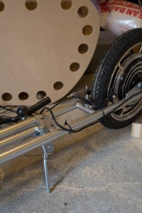
The new kick stand

I plan to stain the bike, but also want a racing stripe.  My theory was that masking tape wouldn’t work as the stain would simply bleed under it, causing a wavy/uneven line.  I was pleasantly surprised by the result – virtually no bleed!  I had to sand the surface to an almost polished finish and use a good quality painters tape, but it worked.  Here you can see a couple of test colours, both masked along a line.  Rimu on the left, Kauri on the right.  I think I will use Rimu for the main colour, and something darker than Kauri – maybe Ebony – for the racing stripe.  I used Wattle Colourwood pigmented stain.  Once the scooter is stained, I plan to get it clear-coated (like an automobile).
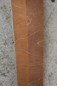
Testing stain colours and masking

Testing the bits

The first step before getting the scooter on the road, and trusting the integrity of my epidermis to the integrity of this contraption, was to put it all together.

The first step was to drill the bolt holes to allow the body to be mounted to the frame.  I placed the body on the frame, clamped the frame, then flipped the body up to get at the frame.

Drilling the mounting holes

Once the holes were drilled (which sounds easier than it actually was), I flipped the body back around, placed it on the frame and bolted it down.  The bolt holes are counter sunk on top and the M6 stainless bolts sit flush with the fairing.

Attaching the body

The next step was attaching all the hardware up.  I drilled a hole (25mm) through the body directly under the battery box.  A second hole allows the cables to run up into the box – these two holes are offset so that water cannot splash directly up.  All cables are cable-tied along the frame to the hole under the body.  There are connections from the motor (power, control), the throttle (throttle, battery indicator, cut-off switch) and the brakes (cut-off).

I then fastened the battery box down with glue and screws, and I was ready to test!

First test drive (YouTube)!

Update: After attaching a GPS, I have measured top speed at around 32 to 33 km/h.

TV has a home

Wife informs me that this project took 3 years and 10 months to complete.  I told her that the last Olympics didn’t seem like it was that long ago, and the TV cabinet was quicker.  She wasn’t impressed.

Here it is. The TV has a new home.  When the cabinet was started, the little man modelling it wasn’t even in the picture!  It features drawers (upper left and right) to hold CDs and DVDs.  Beneath those the doors fold out and down on cabinet style hinges – these to hold the Wii etc.  Tinted glass doors open to reveal an adjustable height shelf.

Many drama’s unfolded and were solved (or cludged) during this build, including:

  • The drawer faces on the left are pine, whereas the rest is Macrocarpa.  They needed to be stained darker to match.
  • One of the internal walls had cut-outs made on the wrong edge before I realised it was turned 90 degrees. The botch-up is at the back 🙂
  • The glass doors were too wide and overlapped in the middle. A local glass company cut them down 2mm each.
  • I cursed and swore at my ‘cheap, useless’ tools for not cutting straight edges when in fact the cabinet was almost 10mm off-square!  Fixing the top in-place rectified that.

But I get to tick another off the list!  What to start next….

Son modelling the new TV cabinet

Upholstering the bits

If this thing is going to be used for the daily commute, I better make sure it is comfortable to sit on. And looks cool.

As with many parts of this project, this will be another ‘first’ – leather upholstery.  Surprisingly, ‘the internet’ does not seem to have a very large wealth of information on this topic.  Maybe I should have got one of those paper things from the local book hiring place.  I decided to wing it.

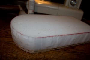
The first step was to cut some foam (left over from a friend, Mike’s, completely kick-ass poker table build) to the required shape, and glue it to the seat base.  I had a simple, retro design in mind with a two-colour racing stripe – which luckily was not that complicated.

The foam cut and glued to the seat base

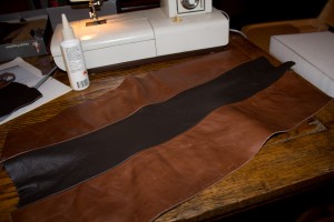
Pulling out the leather supplies from previous projects, I found some suitable pieces in the right colours.  I pulled out the sewing machine and read the manual again.  No, really.  After sewing  a couple of test pieces to get the thread tensions right, I got right on it and sewed up the leather.  The seams were folded over and glued back on the underside to keep them flat (not shown).

Leather sewn and ready for upholstering

Borrowing said-friend’s electric staple gun, I upholstered the seat by stretching the leather over the foam and stapling it into the base. The corners were difficult due to the thickness of several layers of leather where the pleats are folded.  I’m still not happy with them and may add some stitching by hand at a later date.

Here is the finished seat in-place. Yeehaw!

Finished leather seat in place

Shaping the bits

I completed the fairing over the weekend and test-fit it to the scooter. It is really starting to take shape!

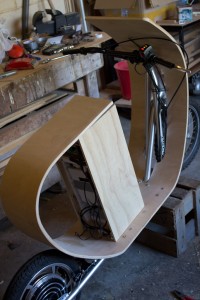
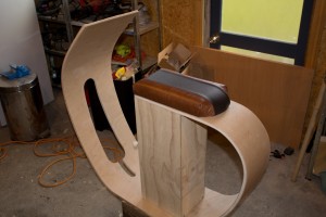
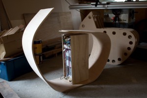
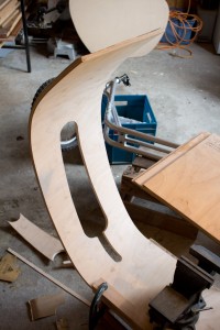
The last lamination was glued up, and after allowing it to cure was removed from the form.  Spring-back was surprisingly minimal, as can be seen below with the battery box in place. Pushing the fairing lightly by hand brings it in to alignment.

Fairing removed from the form

As mentioned in a previous post, laminations are peeling in places where the glue has dried too much and lost its bonding ability before the work was properly clamped.  This is due to using a glue with a short open time (10 minutes).  This will be repaired as much as possible before final assembly by forcing glue into the gaps (some back-bending may be required) and some localised clamping.

Laminations peeling in areas

Next I cut out the shape to fit the tubes that make up the existing scooter frame.  This was done by laying the fairing on its side on top of the scooter and marking where the tubes intersect the fairing.  Big radii were cut with a hole saw and connected using a jigsaw.  Lots of filing and sanding finished the job.

Creating the cut-outs for the frame

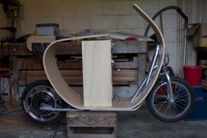
Test-fitting the fairing over the frame shows that the cut-outs are in the right place.  Now we can finally see the (approximate) final shape!

Test-fitting the fairing

Strengthening the bits

Will the scooter be strong enough to stand on?  Hmm. Perhaps not!

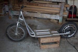
The donor scooter (see second photo) has an existing frame that is perhaps 100mm wide.  The foot board that has been built is about 300mm wide.  The weight of an average human adult would probably fracture the foot board nicely over the frame. Perhaps I should have thought of this sooner?

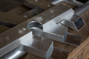
The answer – fabricate a light frame from aluminium to strengthen the foot board.  Ulrich Aluminium supplied some sturdy and inexpensive box section.  I cut two cross members with 45 degree cuts using a regular drop saw with a waxed blade – slowly! – and two longitudinal members to fit over the top of these.  The total aluminium used represents less than $10.

As can be seen in the photo, one of the cross members had to have a section cut away with a hole saw (using CRC as a lubricant on the drill press) to fit around an existing tube on the scooter.  The two longitudinal members had three sides of the box section removed with a hacksaw, file and some elbow grease. Holes were drilled to match existing mounting holes in the scooter frame (for the old plastic foot board).

Fabricated aluminium parts

The frame will be mounted in place (in the position shown in the photo) through existing holes in the scooter frame, and the foot board/fairing mounted to this.  I had to cut away a section of sheet steel that was welded to the rear of the foot board area at an upwards angle.  The first time I have used an angle grinder – the sheer amount of sparks gave me a bit of a fright, but no problems there!

Donor kick scooter showing frame in place

You can see the hub motor in the rear wheel. The whole unit is cast as one piece.  It is also on the right way around now 🙂