Category Archives: ✔ Electric Scooter

I say: A cheap commuter vehicle
Wife says: TV CABINET!

Assembling the bits

I had the newly welded frame of the bike, plus the forks and handle bars, sand-blasted and powder-coated.  The closest colour that they had to chrome is a colour called ‘sparkles’. And yes, it is as disco-barbie as it sounds, with bits of glitter all through it.  It doesn’t look too bad though, as only small parts of the frame are visible.

With almost all the bits on hand – just waiting for the front wheel now, it was time to assemble all (well, most of) the bits.

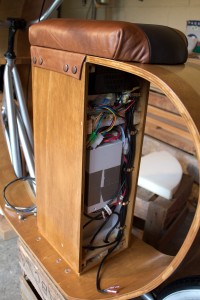
I added some clips inside the box to tidy the wires – not much room in there!  There used to be space at the top, but I have now mounted the battery charger under the seat.

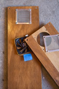
Here are the ends of the battery box, ready to install. In the end there was not even room for the cooling fan, so I have left it out.  Hopefully the airflow through the grills while riding will be enough to keep the parts cool.  The charger has a little fan built-in.

The front grill in place.

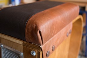
A close-up of the seat, showing the leather flaps added along each side of the battery box.  These are to add a little detailing, and to hide the edge of the seat which is a tiny bit crooked 🙂

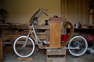
Here is the new 20″ wheel with disk brake mounted to the hub motor.  I haven’t tested the brakes yet, but they should have plenty of stopping power now!  I decided to go for white-wall tyres for a more classic look.  The front wheel (which is on order) is a retro-styled wire wheel with a classic spoke pattern.

Still to do:

  • Hang the front wheel once I get it
  • Make some custom handle bars. The current ones don’t have quite enough range without hitting the fairing
  • Get a new, longer, brake cable (doesn’t reach up to the bars)
  • Mount the brake levers and thumb throttle
And then it is ready to ride.
Some time soon:
  • Source lights and design a 12v lighting circuit
  • Make the badges


Welding the bits

Welding is not currently in my list of practical skills, so I needed some help in this department.  Well, it could be in my list of skills, but Wife wasn’t prepared to let me buy a welder, pipe bender, gas torch and assorted equipment to find out.

The new wheel arrived from China within a week of ordering it (www.aliexpress.com – highly recommend it), and looks like it has all the right bits so that the scooter can finally have working brakes.  The only problem is that the new wheel won’t fit in the current frame. So modifications had to be made.

I sourced some metal tube with the right inside diameter to fit over the existing frame. The guys at Manawatu Muffler Center came to the party with a pipe bender and bent it to shape.  My angle grinder came in handy to cut the pipe to length, and then back to Manawatu Muffler Center for some welding.

Plug: The guys at Manawatu Muffler Center are great – friendly, helpful, and more than happy to help with my project even though it was outside of their normal work. They only charged me a token amount and did a great job.  I wouldn’t hesitate to recommend them if you need any sort of actual muffler work done.  They are building a stock car for the boss’s daughter too, so they obviously had the skills for my job.

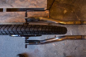
Here is a photo of the new tubes welded on. Perfect.  I just need to clean them up a little with a grinder (new tool! yes!) and repaint the frame to stop rust.

This photo shows the old part of the frame laid on top of the new one.  You can see it is quite a bit wider, and about 50mm longer too.

I found some old pieces of steel lying around the garage and made these new tabs to hold the rear axle.  I love my angle grinder. It makes sparks. So pretty 🙂

And here is a comparison of the new wheel (in the frame) against the old wheel.  I decided to buy a bigger wheel (20″ – BMX size) instead of sticking with the smaller 16″ wheel (kids BMX size).  The old wheel was good for about 32km/h – the bigger wheel should get closer to 40 km/h (25 mph).

Next steps are to attach the disk brakes, paint the frame, coat the fairing/body (UV protection), get a new front wheel the same size as the back one, and put it together.

Staining the bits

Stains aren’t always a good thing, especially brown ones, but when it comes to woodwork they are ok.

On the suggestion of a friend who is building an electric skateboard, I decided to stain the scooter before clear coating it, instead of leaving it as bare timber.  The unfinished timber is birch and is very pale, so I chose a medium dark brown called ‘Rimu’, a native timber found here in New Zealand.

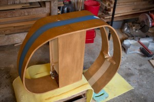
I also wanted a racing stripe, so after a few experiments to check if masking areas worked with wood stain, I proceeded to mask the racing stripe with a good quality painters masking tape.  The stain itself was very easy to apply – it is rubbed in with a clean cloth, and spreads evenly without patching.

Some parts of the scooter are very tight, so I folded the cloth around the end of a flat-head screwdriver to get into those tight spots.

The Rimu colour has a red tint, and is very close to the colour of the leather seat. The photo below is a little deceptive due to the bad lighting in my work space.  The colours are actually much closer under natural light.

The masking tape removed cleanly with almost no discernible bleed, except in areas where the tape was raised slightly because of less than perfect build quality (parts not lining up exactly flush).  Overall, I am happy with the result.  I may end up staining the racing stripe with a very dark stain rather than leaving it as bare timber, so that it matches the seat – not yet sure.


Widening the bits

Having no brakes is not that safe.  I think I may get some.

Well, truth be told, the scooter does have brakes, they are just very, very (very) poor.  When I purchased the original kick scooter and (attempted) to kick it home from work on the day it was delivered, the brakes had no stopping power even then.  Now it is 25kg heavier and 25km/h faster.

So I ordered an e-bike disk brake from the manufacturers of the motor in China.  Only took a week to arrive, which is great!  I now have a shiny new disk brake set-up with nice grippy cable-driven callipers.  And they don’t fit.

The problem is two-fold.

  1. There is no mount for the disk/rotor on the motor
  2. There is no room between the rear forks for the brake installation

The following part of the post is mostly for the benefit of Father, who is a former fitter and turner (engineer).  He’s going to make sure my plans to widen the rear forks are solid, and then hopefully do it for me 🙂  Go Dad!

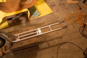
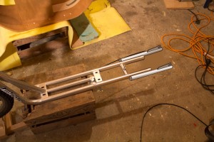
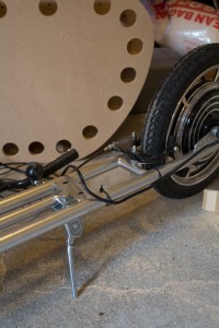
This is the current rear of the frame.  The forks need to be widened slightly (perhaps 60mm) and lengthened (although, not strictly necessary, so even 50mm will do).

This is the current rear frame

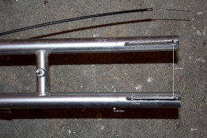
These are the measurements of the rear assembly:

Rear assembly with measurements

And here is my plan to widen and lengthen the forks:

  • Hacksaw off part of the existing tube, including the axle mounts.
  • Take some tube the same diameter as the current frame (28.7mm) and weld it along the outside of the current tubes.
  • Make some new axle mounts (or carefully re-purpose the old ones) and weld them to the new tubes
  • This will give an extra 50mm of length, and extra 57.4mm of width, and removing the end of the existing tube will give extra room for the brake assembly.

Plan for the modified rear end

What do you think dad?  No bending required, and hopefully not that much fabrication.  But will it have the requisite strength?

The important bits

One thing on the electric scooter is vitally more important than all others. What could that be?  The badge, of course!

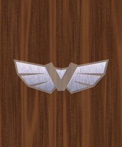
V badge in black and white

Those that know me will see why I chose a ‘V’.  Everyone else, lets just say its along the lines of ‘Volt’ 🙂

V badge

The badge will be constructed of perspex with aluminium bonded to the surface.  LEDs embedded in the perspex under the alu will give a nice, subtle glow. White at the front, red at teh rear.  Not sure on the size yet, but probably around 150mm across.

The boring bits

Not every minute of a project can be packed with excitement. Sometimes, you just have to get on with it.

The biggest excitement on the project by far last week was ‘test driving’ the scooter to work. As I am still a little dubious about the legal requirements, I took a circuitous route down a path along the local river.  Unfortunately, the section I chose to take was not sealed, and I ended up losing my nuts.  Erm.  I mean, some of the nuts came off the bolts holding the fairing to the frame.  This wasn’t a biggie – there are quite a lot of bolts holding the scooter together.  The final construction will use nyloc nuts.  Some observations:

  • The ride quality is great (except on gravel).
  • Torque was fantastic, even hitting maximum speed uphill.
  • Maximum speed was around 32 km/h. Not complaining, really.
  • The brakes are not that good. Yes, this one is a complaint.
  • The handlebars, already at maximum extension, are a little low.
  • There is not quite enough area for feet. It needs pegs.
  • There is no stand. A problem once I got to work! (No beer crates to lean on – will work on that).

After the fun day test-driving, I took the scooter completely apart again.  The plan is that next time it goes back together will be the final time (with nyloc nuts).  Once again I spent some time repairing peeling laminations that the rigours of the drive bought to light.

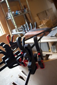
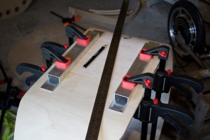
Localised clamping to fix peeling laminations

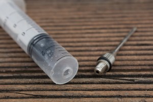
I managed to construct a fairly good glue applicator needle from a 10ml plastic syringe with the nozzle cut off and a ball-pump needle screwed in to the hole!  This fits easily into small gaps and allows me to spread the glue well before clamping.  I use a plastic off-cut from a takeaway container as a spatula to spread the glue in the crack.

Home-made glue applicator needle

Detail of the glue applicator needle

K-Mart supplied a cheap, generic, extendible kick stand.  On testing it, it was miles too long, so I threw away the extension and put the hacksaw to use making it shorter.  My plan is now to buy another one, cut it the same and put it on the other side.  They are the right length to stand the bike vertically (rather than leaning).  I may also look at some sort of steering lock so that the front wheel doesn’t move while parked.

The new kick stand

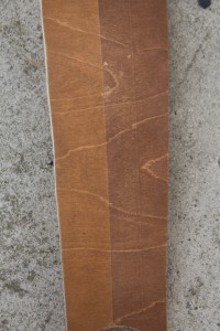
I plan to stain the bike, but also want a racing stripe.  My theory was that masking tape wouldn’t work as the stain would simply bleed under it, causing a wavy/uneven line.  I was pleasantly surprised by the result – virtually no bleed!  I had to sand the surface to an almost polished finish and use a good quality painters tape, but it worked.  Here you can see a couple of test colours, both masked along a line.  Rimu on the left, Kauri on the right.  I think I will use Rimu for the main colour, and something darker than Kauri – maybe Ebony – for the racing stripe.  I used Wattle Colourwood pigmented stain.  Once the scooter is stained, I plan to get it clear-coated (like an automobile).

Testing stain colours and masking

Testing the bits

The first step before getting the scooter on the road, and trusting the integrity of my epidermis to the integrity of this contraption, was to put it all together.

The first step was to drill the bolt holes to allow the body to be mounted to the frame.  I placed the body on the frame, clamped the frame, then flipped the body up to get at the frame.

Drilling the mounting holes

Once the holes were drilled (which sounds easier than it actually was), I flipped the body back around, placed it on the frame and bolted it down.  The bolt holes are counter sunk on top and the M6 stainless bolts sit flush with the fairing.

Attaching the body

The next step was attaching all the hardware up.  I drilled a hole (25mm) through the body directly under the battery box.  A second hole allows the cables to run up into the box – these two holes are offset so that water cannot splash directly up.  All cables are cable-tied along the frame to the hole under the body.  There are connections from the motor (power, control), the throttle (throttle, battery indicator, cut-off switch) and the brakes (cut-off).

I then fastened the battery box down with glue and screws, and I was ready to test!

First test drive (YouTube)!

Update: After attaching a GPS, I have measured top speed at around 32 to 33 km/h.

Upholstering the bits

If this thing is going to be used for the daily commute, I better make sure it is comfortable to sit on. And looks cool.

As with many parts of this project, this will be another ‘first’ – leather upholstery.  Surprisingly, ‘the internet’ does not seem to have a very large wealth of information on this topic.  Maybe I should have got one of those paper things from the local book hiring place.  I decided to wing it.

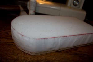
The first step was to cut some foam (left over from a friend, Mike’s, completely kick-ass poker table build) to the required shape, and glue it to the seat base.  I had a simple, retro design in mind with a two-colour racing stripe – which luckily was not that complicated.

The foam cut and glued to the seat base

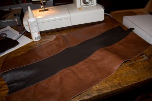
Pulling out the leather supplies from previous projects, I found some suitable pieces in the right colours.  I pulled out the sewing machine and read the manual again.  No, really.  After sewing  a couple of test pieces to get the thread tensions right, I got right on it and sewed up the leather.  The seams were folded over and glued back on the underside to keep them flat (not shown).

Leather sewn and ready for upholstering

Borrowing said-friend’s electric staple gun, I upholstered the seat by stretching the leather over the foam and stapling it into the base. The corners were difficult due to the thickness of several layers of leather where the pleats are folded.  I’m still not happy with them and may add some stitching by hand at a later date.

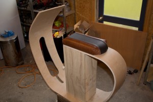
Here is the finished seat in-place. Yeehaw!

Finished leather seat in place

Shaping the bits

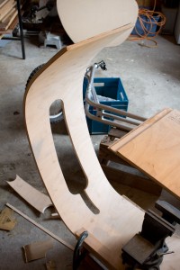
I completed the fairing over the weekend and test-fit it to the scooter. It is really starting to take shape!

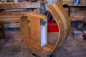
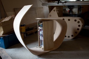
The last lamination was glued up, and after allowing it to cure was removed from the form.  Spring-back was surprisingly minimal, as can be seen below with the battery box in place. Pushing the fairing lightly by hand brings it in to alignment.

Fairing removed from the form

As mentioned in a previous post, laminations are peeling in places where the glue has dried too much and lost its bonding ability before the work was properly clamped.  This is due to using a glue with a short open time (10 minutes).  This will be repaired as much as possible before final assembly by forcing glue into the gaps (some back-bending may be required) and some localised clamping.

Laminations peeling in areas

Next I cut out the shape to fit the tubes that make up the existing scooter frame.  This was done by laying the fairing on its side on top of the scooter and marking where the tubes intersect the fairing.  Big radii were cut with a hole saw and connected using a jigsaw.  Lots of filing and sanding finished the job.

Creating the cut-outs for the frame

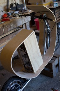
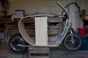
Test-fitting the fairing over the frame shows that the cut-outs are in the right place.  Now we can finally see the (approximate) final shape!

Test-fitting the fairing